Difference Between Parallel and Series Funny
Tutorial on schematics basics
The funny thing about schematics is that they are much easier to draw than they are to read. There are many common circuits. When an experienced engineer looks at them, it's like a second language. When someone less experienced looks at them, it looks like random lines and symbols thrown together at the last-minute. (Or maybe that's just the schematics *I* draw.)
Other than reading Schematic Symbols themselves, one of the basic skill necessary to read a schematic is recognizing series and parallel circuits.
In short if the same current flows through all the parts, they are in series. While if current has different paths, they are in parallel. Keep reading to dive into this tutorial on how ohm's law applies to series and parallel circuits.
Starting with some Basic Definitions
There are a couple of definitions we need to go through, before talking about series and parallel. These are all terms that get thrown around when people describe circuits, so let's start at the same reference point. A ground if you. (sorry, bad pun.)
Circuit

Okay, this seems like an obvious one to engineers, but probably needs definition for non-engineers. In electronics a circuit is aclosed path electrons flow around. So that means there needs to be a start and end point, and that those points must be connected together. For example a simple wire could be a circuit or connect a battery to a resistor and you have a circuit.
Voltage Drops
Voltage is a difference in potential between two points. Now in the case of Figure 1, there is only one part, so all the voltage "drops" across it. Let's say the positive side of the battery is 10V, then means the negative side is 0V. So that means one side of the resistor is at 10V while the other side is at 0V. Subtract those two numbers: 10V – 0V = 10V to find that the resistor has avoltage drop of 10 volts.
All voltage drops must add up.
Current Loops
As mentioned in the Circuit definition, current needs a loop. So all the current that leaves the positive side of our battery (or whatever voltage source) must also return to the negative side. In other words, the currentloops from the battery's positive into the resistor, out of the resistor, and back into the battery.
All current out must equal all current in.
Series Circuit
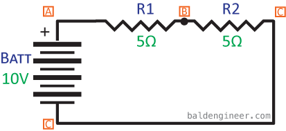
When components are connected one after another, it is called a series circuit. Figure 1 is a simpleseries circuit with two components: a battery and a resistor. To make things more interesting, let's add another resistor to the mix. That brings us to Figure 2, below.
Voltage Drops in Series circuits
In Figure 2's circuit the battery is providing 10V. The total voltage drop across both resistors (points A to C) is going to be 10V. However, what is the voltage drop across just R1 (from points A to B) going to be? It can't be 10V, because then that means point A is at 10V making point B be 0V. In the case of this circuit, because both resistors are the same resistance value (5ohms), the voltage is split. So Point B is actually at 5V, meaning the voltage drop of both R1 and R2 are each 5V.
The voltage drop of R1 (5V) plus the voltage drop of R2 (5v) equals 10V.
Current Loops in Series Circuits
If all the electrons (current) leaving the battery at Point A must also return to point C, what does this mean for the current through the resistors? It means that the current for R1 is the same as R2. Using Ohm's Law (here is a refresher on Ohm's Law), we can calculate what the total current of the circuit would be:
$latex Current=\frac{V_{Batt}}{R1+R2}=\frac{10V}{5\Omega+5\Omega}=1Amp&s=4$
You can turn that around a bit and calculate the voltage drop for R1. We know it is 5Ω and it has 1A flowing through it, so Ohm's Law says:
$latex Voltage=Resistance\times Current=5\Omega\times 1A=5V&s=4$
Parallel Circuit
Connecting components so that multiple points are connected together, puts them in parallel with each other, like shown in Figure 3.
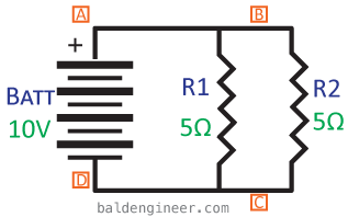
When components are in parallel, the way that voltage drops and current loops add up, change.
Voltage Drops in Parallel Circuits
Notice that Points A and B of Figure 3 are actually the same line. Also notice that points C and D are also the same line. This means the voltage drop across R1 and R2 is actually going to be the same. So the voltage drop across R1 is 10V and the voltage drop across R2 is also 10V!
Current Loops in Parallel Circuits
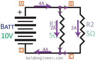
For current to have a loop, all current leaving one point must come back at another point. However, when components are in parallel, the current actually splits up inside of the circuit and then recombines later. This means only some of the circuit's total current will flow through R1 and through R2.
Using Ohm's Law, we can see that the current through R1 is going to be 2A.
$latex Current_{R1}=\frac{Voltage}{Resistance}=\frac{10V}{5\Omega}=2Amps&s=4$
And since R2 is the same resistance with the same voltage drop as R1, it will also have 2A flowing through it. This means the circuit's total current is 4A. To help visualize how the current flows in the parallel circuit, take a look at Figure 4.
Here's an interesting twist on what happens with resistors in parallel. Their total resistance drops, as shown when you calculate Resistance with Ohm's Law knowing the total circuit current and voltage.
$latex R_{total}=\frac{V_{Batt}}{C_{total}}=\frac{10V}{4A}=2.5\Omega&s=3$
Combining Series and Parallel
So what happens when you combine series and parallel circuits? You have to do a little work to figure out the effective circuit.
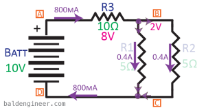
Take a look at Figure 5. It shows an example where R1 and R2 are in parallel with each other, but R3 is in series with that parallel combination.

From the previous example, we have an equation to calculate the resistance of two resistors in parallel. Use that and we find the two 5Ω resistors in parallel with each other have an effective resistance of 2.5Ω. Now that we know that, the effective circuit becomes R3 in series with 2.5Ω. Figure 6 shows what this effective circuit looks like.
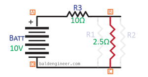
To solve for the circuit's total voltage and current, we use 10V as the voltage and 12.5Ω as the total resistance. This means the total current in the circuit is 0.8A or 800mA. Since R3 is in series with R1 and R2, we know that 800mA has to flow through R3. However, only 400mA will go through each R1 and R2.
$latex V_{R1}=5\Omega times 400mA=2V&s=3$
$latex V_{R1}=5\Omega times 400mA=2V&s=3$
$latex V_{R3}=10\Omega times 800mA=8V&s=3$
Figure 7 shows the current and voltage for each resistor in this combination circuit.
What's the toughest circuit you've had to solve so far?
Source: https://www.baldengineer.com/series-and-parallel-circuits-tutorial.html
Belum ada Komentar untuk "Difference Between Parallel and Series Funny"
Posting Komentar